Thanks!
Parker Pens
http://www.parkerpen.com/
Shanghai Hero Group
http://en.hero.com.cn/
Ernesto Soler's encyclopedian Parker 51 site
http://www.parker51.com/
The endless horrors of the World of Kitch website
http://theworldofkitsch.com/tasteless-1970s-indoor-water-fountain
The vacumatic wikipedia page
http://en.wikipedia.org/wiki/Parker_Vacumatic
Ariel Kullock's site - custom made 51s. Wowee-wow-wow!
http://arielkullock.com/
Prather Pens - Wowee-wow-wow! (with Christopher Walken's inflection, not Borat's)
http://www.pratherpens.com/
Torelli Pens - Wowee-wow-wow! (see above)
http://torellipens.com/
The Red Cross
http://www.redcross.org.uk/
TemeCycles eBay store, cheap Woods valves
http://myworld.ebay.co.uk/temecycles/
Maidstone Aquatics eBay store, for the aquarium sealant
http://stores.ebay.co.uk/Maidstone-Aquatics?_trksid=p4340.l2563
Cathedral Pens for the vacumatic diaphragm
http://www.cathedralpens.co.uk/index.php?main_page=index&cPath=10_32&zenid=fcelvbkv4phnuiajo04n3tqbm7
Ralph Prather's fascinating FPN post showing a photograph of an autopsied vacumatic Parker 51, illustrating the barrel's diaphragm cavity.
http://www.fountainpennetwork.com/forum/index.php?/topic/214070-custom-51s-in-damascus-stainless-steel/
Connely's level raising solution.
http://www.youtube.com/watch?v=B7cw_9AT5hg
David Armstrong's excellent step by step teardown of a Parker 51 vacumatic filler unit - could have been tailor made for guiding this project. Outstanding!
http://www.restorersart.com/breaking-down-a-parker-vacumatic-filler-unit/
Penfisher's clever pellet-socket-from-a-ballpoint-pen FPN post.
http://www.fountainpennetwork.com/forum/index.php?/topic/165864-vac-pellet-pocket-help/page__view__findpost__p__1656873
Ernst's page at Ravensmarch, on diaphragm replacement - especially useful for ascertaining the correct diaphragm length (long enough to fully extend, but not stretch).
http://dirck.delint.ca/beta/?page_id=720
Hennypenny's FPN post mentioning the use of aquarium sealant to block breather holes in eyedropper conversions
http://www.fountainpennetwork.com/forum/index.php?/topic/67101-lamy-vista-eyedropper-conversion/page__view__findpost__p__1259932
David Nishimura's Seven Deadly Sins of Vacumatic Repair
http://www.vintagepens.com/FAQrepair/sins_Vacumatic_filler_repair.shtml
Captain Flint's joyful rendition of Yo-Ho (It's a Pirate's Life For Me), on permanent loop as I typed up this series of posts.
http://www.youtube.com/watch?v=GSQDh6e3axc
No Thanks!
Blogger! Why do I have to fiddle with the HTML to place two photographs side by side, with word wrapped caption text for each? Contemporise, man!
YouTube, I do wish you had some sort of offline software available to reencode large files.
Tuesday 4 September 2012
Hero 616 Vacumatic (7) - Installing the Complete Filler Unit
Installing the filler completes the vacumatic 616 build (though it's all about the journey, man). This takes about 5 minutes to do, then strictly 48 hours of resisting the urge to press that shiny plunger/ letting the sealant cure.
Bringing together the filler and the pen was quite the conundrum for a while. As mentioned earlier, the 616's barrel lacks a vacumatic Parker's dedicated inner contours. To compound the issue, the cross section of the barrel is not quite circular, like a gibbous moon.
In her first sea trials, this gave the filler big problems maintaining an airtight seal. Of course, with the slightest air gap, no vacuum could be generated. I puzzled over this for several evenings. Some sort of deformable gasket, or packing? Too rigid. Wraps of teflon tape around the top of the filler? Too fragile. Try to hone the cavity true? Too involved. The Ultragrey left over from changing the blasted Civic's rocker cover gasket? Quite messy, and too costly.
Sometimes epiphanies don't strike; with a shrug, I put all the bits in a ziplock baggie, all the photos in a folder, and didn't think about the project again for 5 months.
I won't bore you with this for too much longer; the answer was there all along, had I the insight to look for it - aquarium sealant. People have used it to plug up vents in eyedropper conversions for several years. I've no interest at all in eyedroppers, and my regrettable lack of curiosity almost killed off this vacumatic conversion.
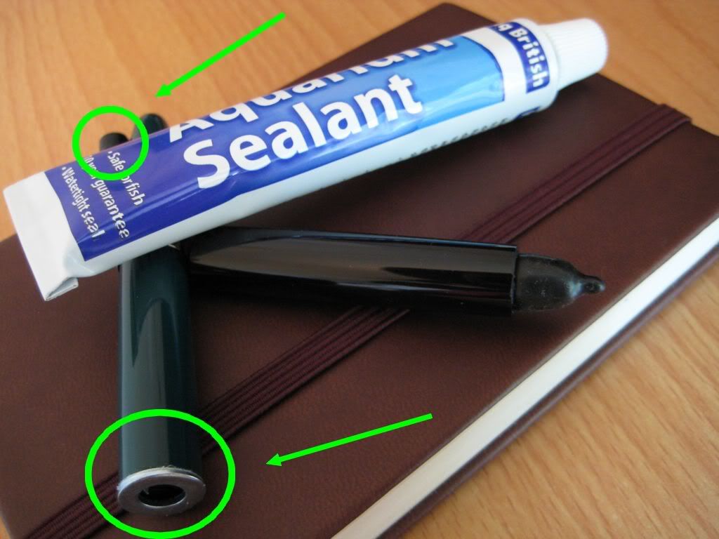
Still, better late than never! I picked up some aquarium sealant from eBay, and was suitably impressed. It goes on with with the consistency of a thick grease, and cures to form a strong waterproof bond (as well it should to mount valves to fish tanks).
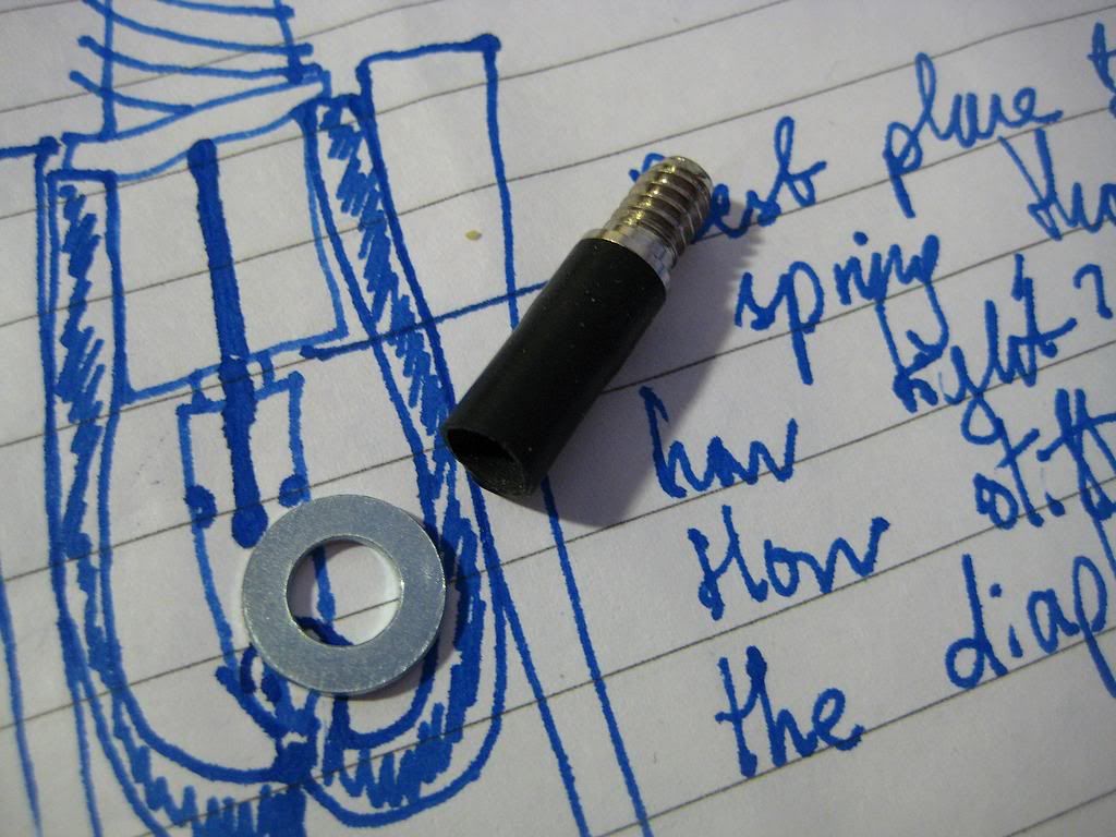
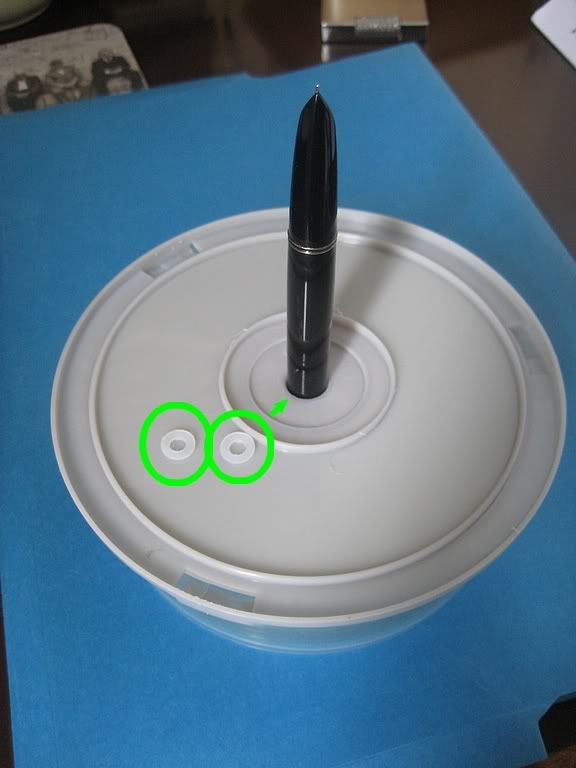
In a test of its capabilities, I used the sealant to stick an ink sac off-cut and steel washer to another 616 barrel. After 2 days, the steel washer took quite some effort to pull off, while the ink sac almost tore rather than separate from the plastic, despite being sealed to the barrel side on (like this 00).
I found that the 48 hour dry time has its advantages. You don't have to rush during application, and any excess sealant can be wiped off well before it has a chance to set - even peeled off after the first few hours. I could afford to be very liberal with this stuff when mounting the filler -application was with the eye of a large needle. Notice the lack of talcum powder in the photo below. There's loads within the diaphragm, and none without, so as not to interfere with the sealant.
Adapting the advice on the vacumatic tear down page at the Restorer's Art site, I then lubricated the barrel (rather than the diaphragm). This meant I could leave a decent sized clean & dry area at the top of the barrel for the sealant to adhere to. A cotton bud soaked in soapy water, inserted from the bottom of the barrel, performed this job.
Here's the filler in place, before setting aside to allow the sealant to cure.
That's all, folks! Despite the delays, I had a blast visiting the many great sites on vacumatics, giving it a go, and eventually watching the bubbles form as the assembled pen began to fill. This aeromatic to vacumatic conversion is the last in this 3 part series of articles on Hero's 616 Jumbo, did you enjoy it?
Until next time, thanks for reading!
Flounder
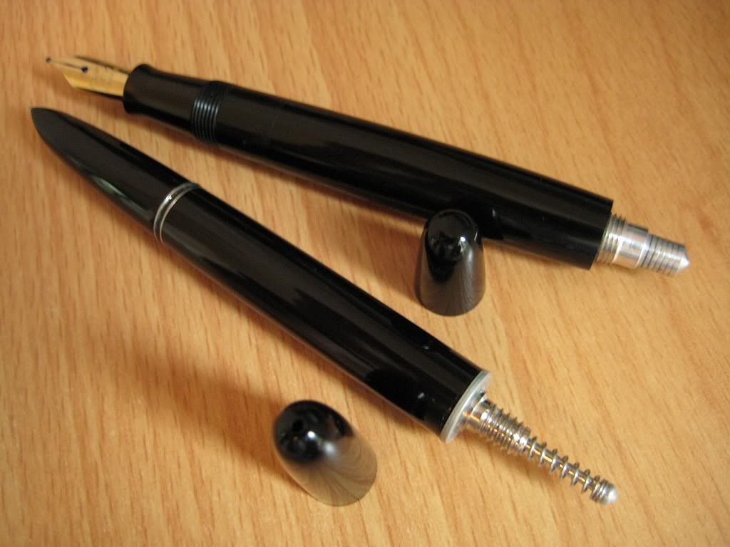 |
| Foreground: A 616 Jumbo with the vacumatic filler installed. |
Bringing together the filler and the pen was quite the conundrum for a while. As mentioned earlier, the 616's barrel lacks a vacumatic Parker's dedicated inner contours. To compound the issue, the cross section of the barrel is not quite circular, like a gibbous moon.
 |
| The 616's thick barrel wall makes a strong platform for the filler housing; its irregular circumference is less helpful. |
In her first sea trials, this gave the filler big problems maintaining an airtight seal. Of course, with the slightest air gap, no vacuum could be generated. I puzzled over this for several evenings. Some sort of deformable gasket, or packing? Too rigid. Wraps of teflon tape around the top of the filler? Too fragile. Try to hone the cavity true? Too involved. The Ultragrey left over from changing the blasted Civic's rocker cover gasket? Quite messy, and too costly.
Sometimes epiphanies don't strike; with a shrug, I put all the bits in a ziplock baggie, all the photos in a folder, and didn't think about the project again for 5 months.
 |
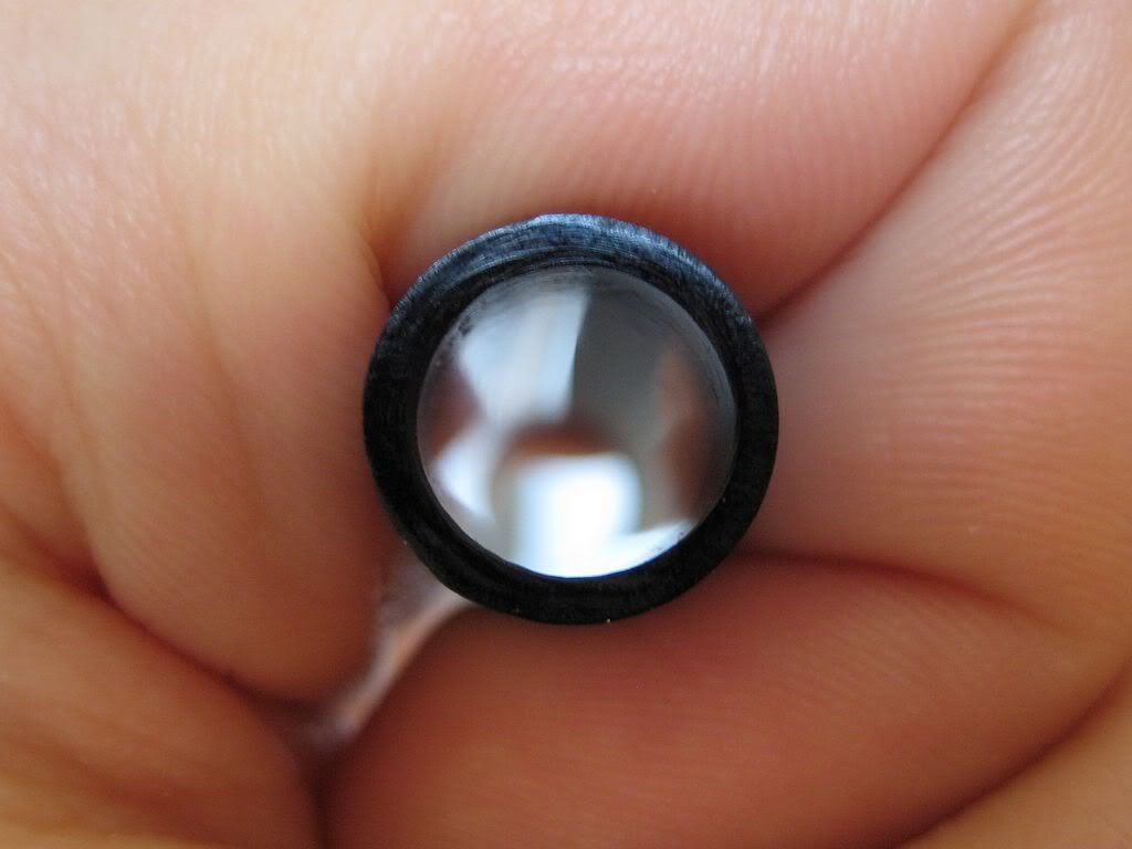
| Highlighted: rubber ink sac and steel washer sealed to a 616's plastic barrel. |
Still, better late than never! I picked up some aquarium sealant from eBay, and was suitably impressed. It goes on with with the consistency of a thick grease, and cures to form a strong waterproof bond (as well it should to mount valves to fish tanks).
In a test of its capabilities, I used the sealant to stick an ink sac off-cut and steel washer to another 616 barrel. After 2 days, the steel washer took quite some effort to pull off, while the ink sac almost tore rather than separate from the plastic, despite being sealed to the barrel side on (like this 00).
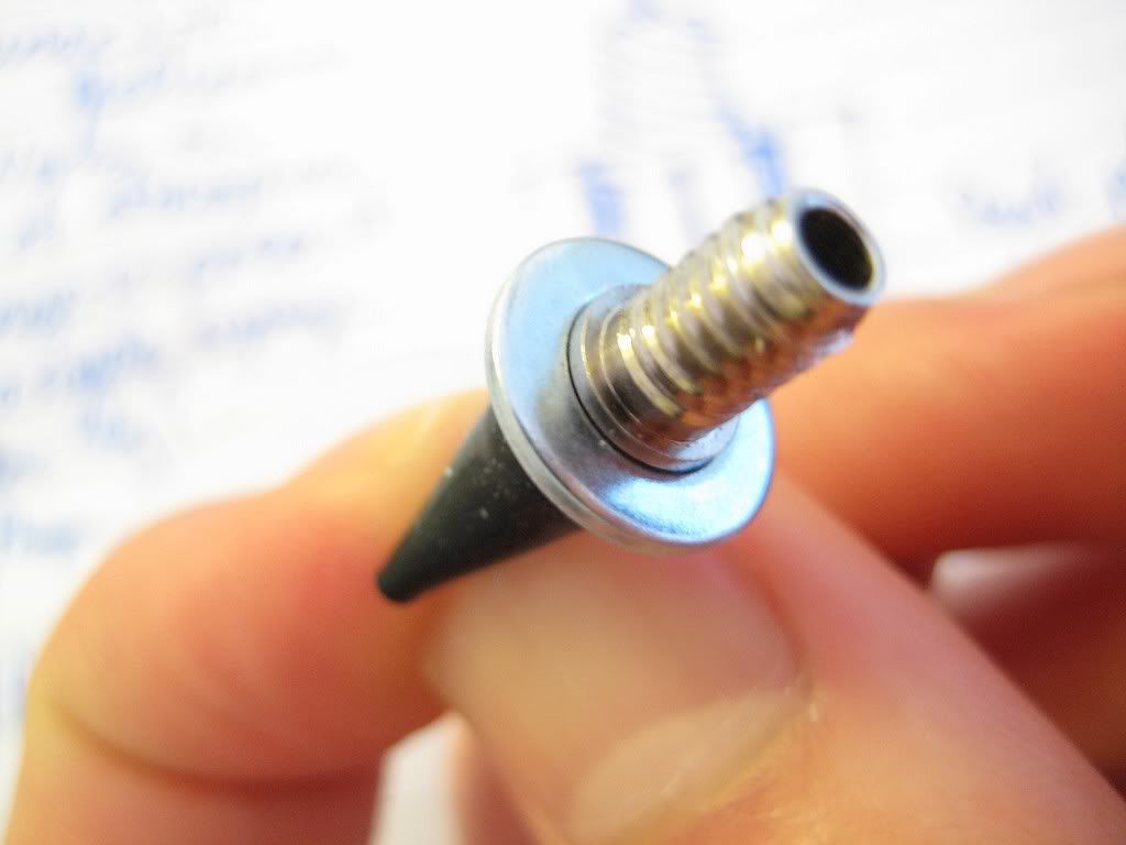
I found that the 48 hour dry time has its advantages. You don't have to rush during application, and any excess sealant can be wiped off well before it has a chance to set - even peeled off after the first few hours. I could afford to be very liberal with this stuff when mounting the filler -application was with the eye of a large needle. Notice the lack of talcum powder in the photo below. There's loads within the diaphragm, and none without, so as not to interfere with the sealant.
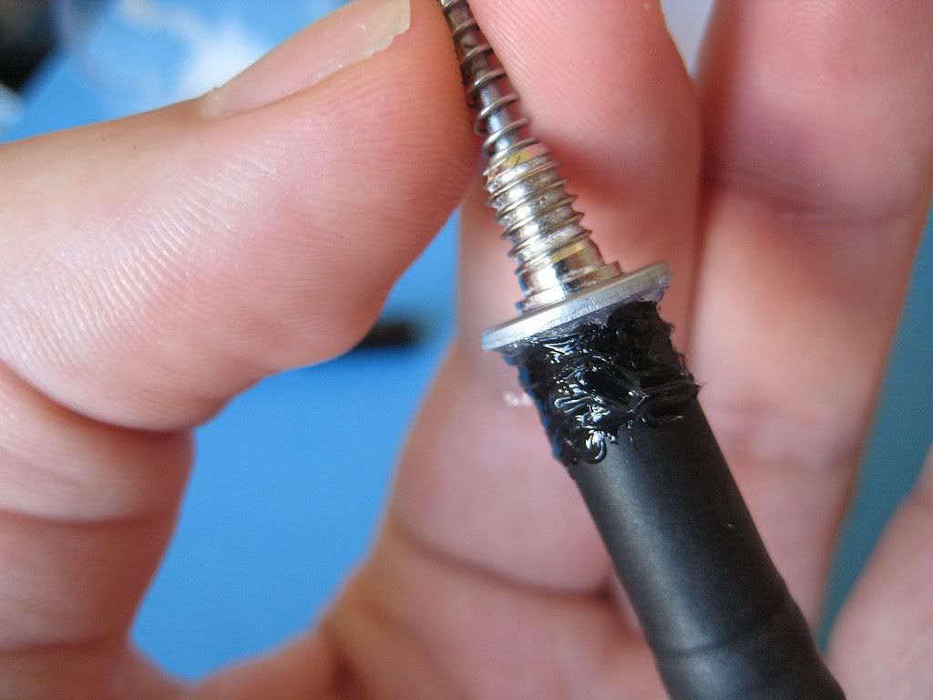 |
| A thick layer of sealant, covering a fair length of the unflexing area of the diaphragm and steel washer for peace of mind. |
Adapting the advice on the vacumatic tear down page at the Restorer's Art site, I then lubricated the barrel (rather than the diaphragm). This meant I could leave a decent sized clean & dry area at the top of the barrel for the sealant to adhere to. A cotton bud soaked in soapy water, inserted from the bottom of the barrel, performed this job.
 |
| Lubricating the barrel with soapy water helped the rubber diaphragm slide into the barrel rather than bind halfway up. |
 |
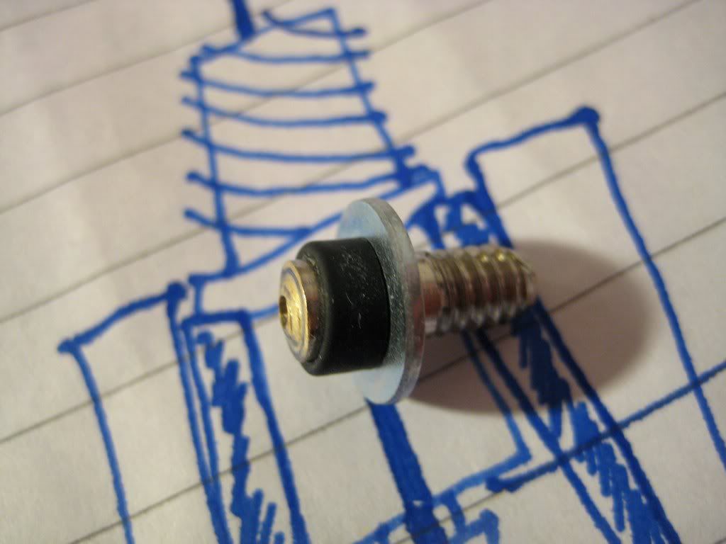
| The filler shortly after installation, with the majority of excess sealant wiped away. |
That's all, folks! Despite the delays, I had a blast visiting the many great sites on vacumatics, giving it a go, and eventually watching the bubbles form as the assembled pen began to fill. This aeromatic to vacumatic conversion is the last in this 3 part series of articles on Hero's 616 Jumbo, did you enjoy it?
Until next time, thanks for reading!
Flounder
Hero 616 Vacumatic (6) - Fitting the Diaphragm
Like conventional ink sacs, vacumatic diaphragms are supplied long, and need trimming to size. This is a very good thing, because this crudely self built vacumatic filler is nowhere near as compact as the optimised examples found in real Parkers. Consequently, the diaphragm needs to be kept longer - here's a photo with the trimmed diaphragm fitted to the filler, to show what I mean. Even at rest, the 616 filler takes up more barrel space than the ideal.
The correct length was figured out by hooking the diaphragm up to the pellet holder (turning it inside out like a sock on laundry day), then pressing the plunger. As it turned out, the diaphragm had about 5mm that it could safely lose without stretching the rubber at full extension.
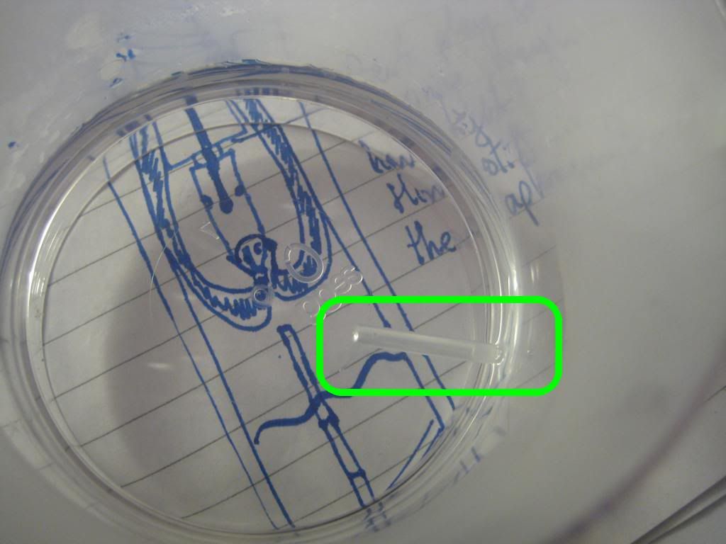
To demonstrate the diaphragm's length, and the plunger's range of motion, here's a short YouTube clip (sorry about the unhelpful angle).
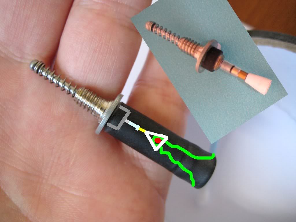
To fit the diaphragm to the filler, I stuck a length of ballpoint ink tube up its backside, to get the (red) pellet clicked firmly in the (white) pellet holder.
After attaching the diaphragm, I gave it a very generous dose of talc, to help convince the rubber to invert properly.
It's a bit messy with so much talc involved, but I found the more talc used, the easier it was to invert the diaphragm. Here's the completed vacumatic filler with diaphragm installed, ready to be fitted to the Hero 616 in the final post of this series.
Next up - you guessed it - installing the filler.
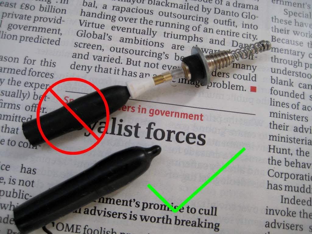
 |
| The 616's diaphragm is kept quite long, to allow for the length of the vacumatic filler. The green area of the x ray is supposed to represent the inverted portion of the diaphragm. Stop laughing at the back! |
The correct length was figured out by hooking the diaphragm up to the pellet holder (turning it inside out like a sock on laundry day), then pressing the plunger. As it turned out, the diaphragm had about 5mm that it could safely lose without stretching the rubber at full extension.
 |
| About 5mm of diaphragm for the chop. The excess was used in the blind cap's construction. |
To demonstrate the diaphragm's length, and the plunger's range of motion, here's a short YouTube clip (sorry about the unhelpful angle).
To fit the diaphragm to the filler, I stuck a length of ballpoint ink tube up its backside, to get the (red) pellet clicked firmly in the (white) pellet holder.
 |
| A length of the biro's ink tube can be used as a makeshift ramrod, pushing the tiny red pellet at the top of the diaphragm into the pellet holder. |
After attaching the diaphragm, I gave it a very generous dose of talc, to help convince the rubber to invert properly.
 |
| The diaphragm secured to the bottom of the plunger rod... |
 |
| ... and liberally powdered with talc. |
It's a bit messy with so much talc involved, but I found the more talc used, the easier it was to invert the diaphragm. Here's the completed vacumatic filler with diaphragm installed, ready to be fitted to the Hero 616 in the final post of this series.
Next up - you guessed it - installing the filler.
Monday 3 September 2012
Hero 616 Vacumatic (5) The Filler Plunger
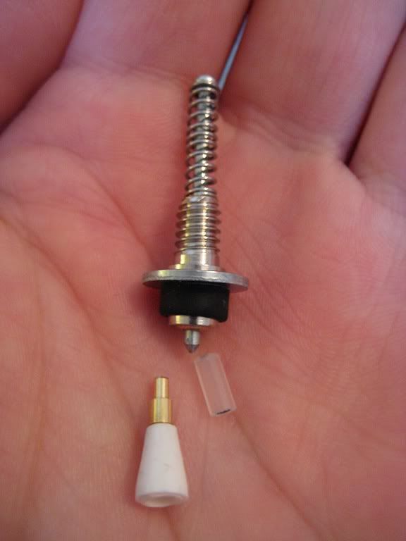 | |||||||||||||
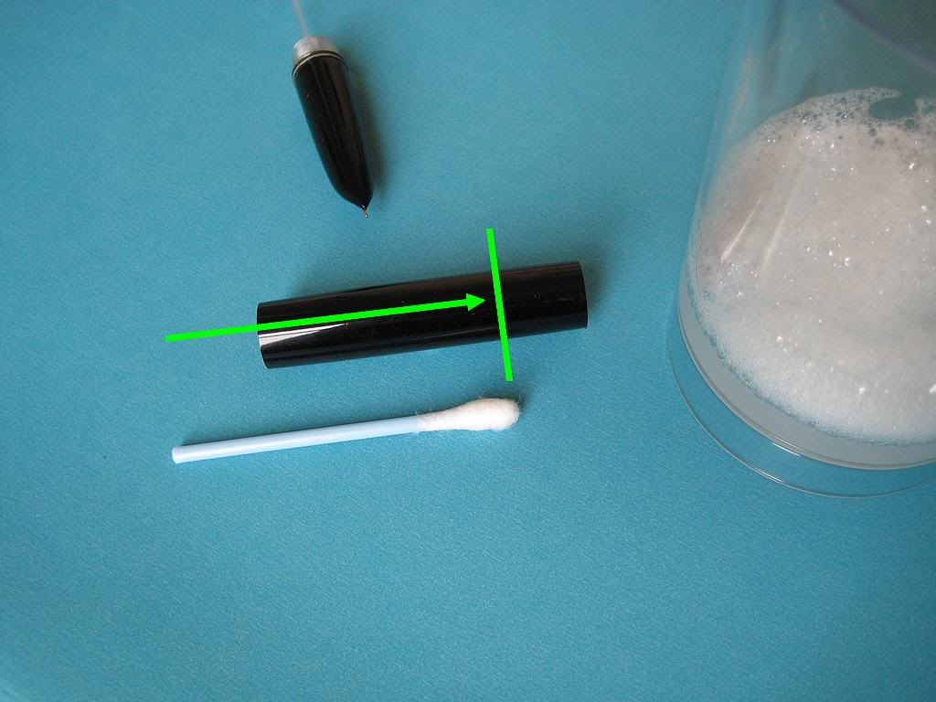
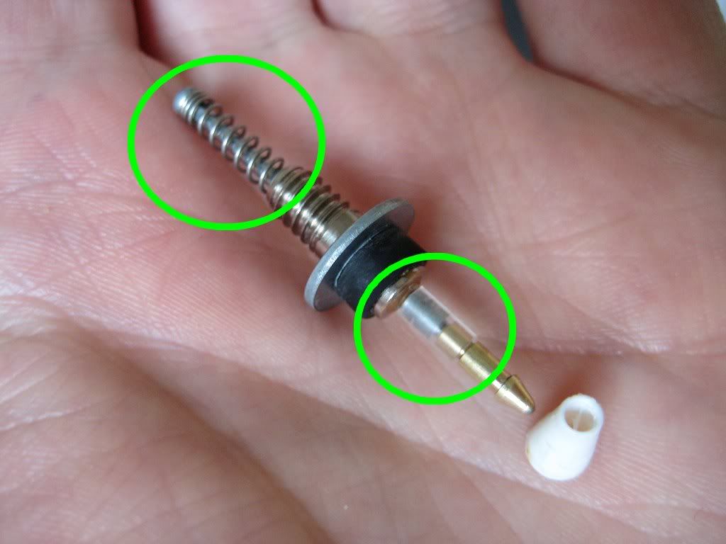
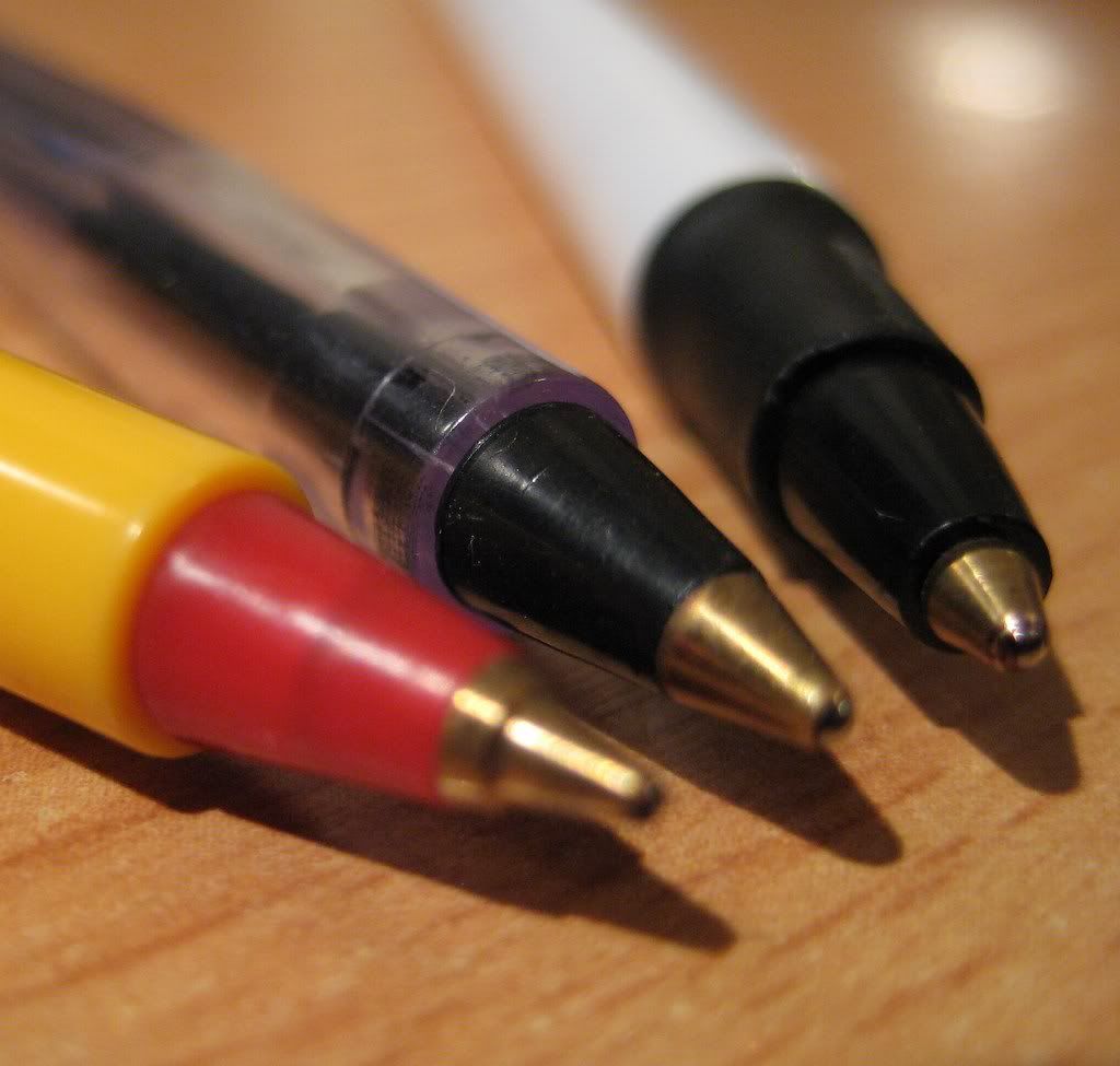
| Below the filler housing - the protruding end of the plunger rod, clear tube connector, golden ballpoint tip, and pellet holder. |
The plunger rod's job is to keep ahold of the rubber diaphragm within the barrel, and give it a good push and pull. A ballpoint pen makes very light work out of the real hurdle in making a lowly 616 vacumatic when it has no business being so; how to make this plunger rod grip the diaphragm.
I had read David Armstrong's excellent Haynes-style dismantling of a real Parker vacumatic filler unit with great interest, gaining a much clearer understanding of how this could be accomplished. In every vacumatic diaphragm, there is a small rigid pellet, housed in a wee pocket at the top. In a real Parker vacumatic, this rigid area gives the mechanism something to hold onto. A dedicated, precisely sized pellet holder glued to the bottom end of the plunger rod does the job.
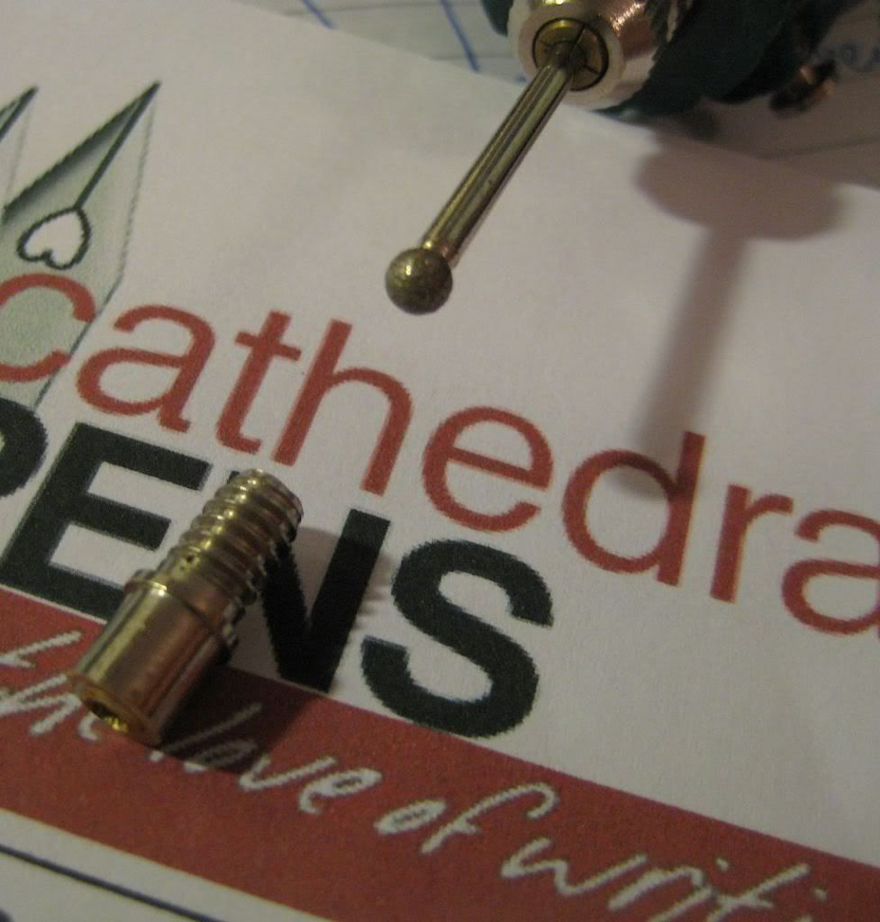
The inspiration to look at ballpoints for this task came from an old FPN post of PenFisher's, on making spare pellet holders for use in genuine Parker vacumatic filler units. This involved cutting out a cross section from a tapered Papermate Writebros ballpoint pen. For my purposes, the British Red Cross freebie ballpoint's design makes it even easier still, as the only cut you need to make is across a straight ridge. It could have been made with this conversion in mind, it's that perfect (I like to think this was a purposeful subversion by some shadowy cabal of renegade designers). Here's a short video, showing a test of the pellet holder's strength. It actually compresses the plunger return spring before letting go of the diaphragm.
As all the parts here discussed came from the same ballpoint, they all snap together securely. The pellet holder clicks into the metal tip of the ballpoint, which clicks into a short length of the rigid ballpoint ink tube. When heated in boiling water, the tube softens enough to have the steel blind rivet tang driven into it. After cooling, they are so strongly connected that it takes two sets of pliers to separate them!
To break that fevered gibbering down into a coherent build sequence, I'll start with the ballpoint pen in hand.
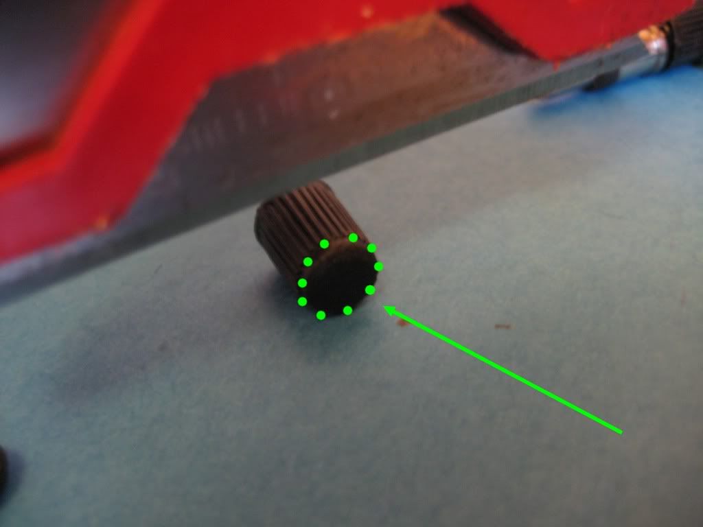
 | ||||||||
| A mailshot British Red Cross ballpoint pen. The area highlighted in green became the pellet holder. |
 |
| Pulling the ballpoint pen apart. Notice how little ink the tube is actually filled with. Good to see the Red Cross aren't wasting too much cash on this sort of thing. |
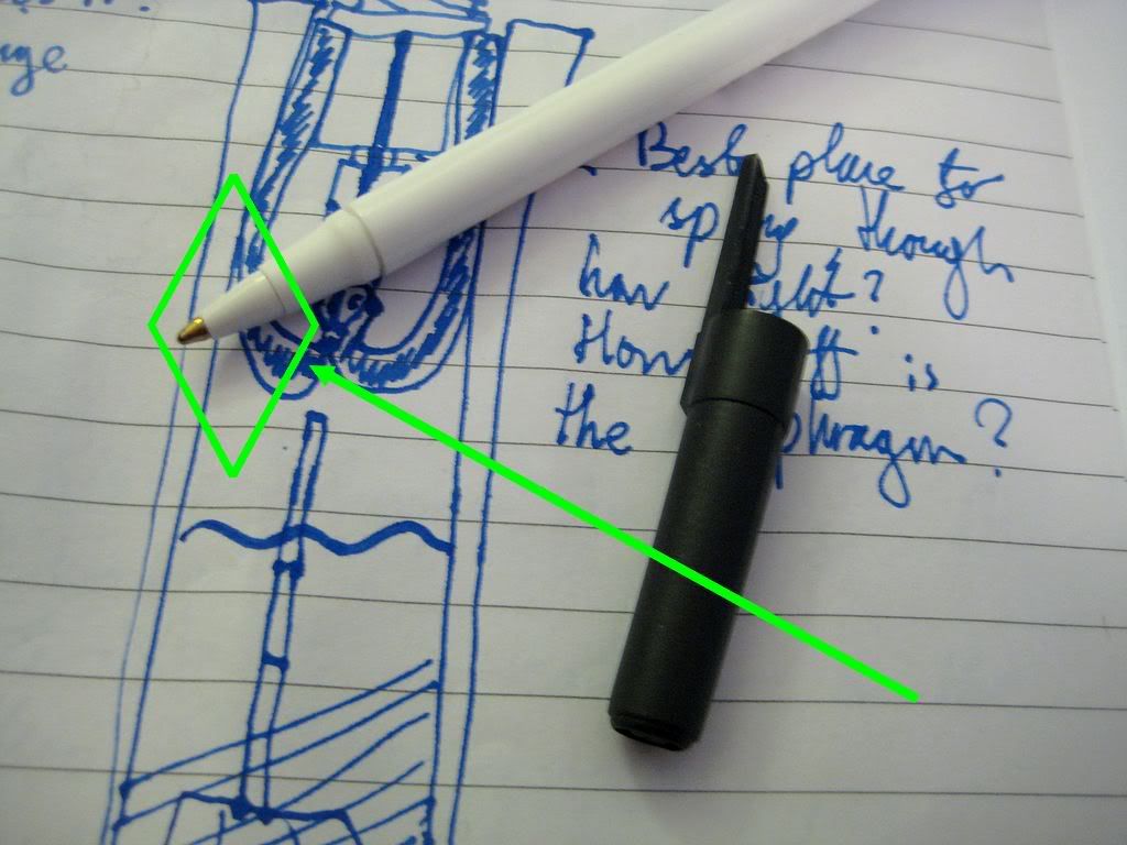
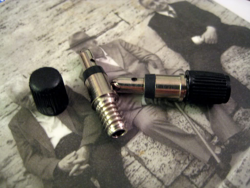
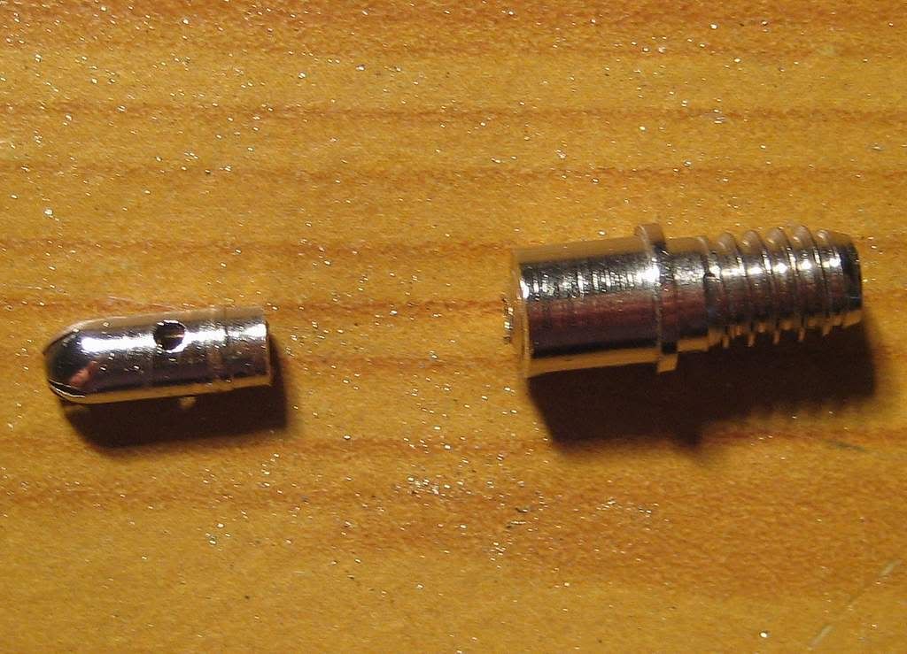
The golden metal ballpoint tip needs to be taken out, and reinstalled the other way around - as shown in this post's first photograph. It is easiest to push it against a hard surface, straight into the plastic surround - it will drop out the other end. Then cut off the end off the plastic piece, straight across the ridge highlighted in orange.
 |
| To release the tip, press it into the plastic surround. |
 | ||
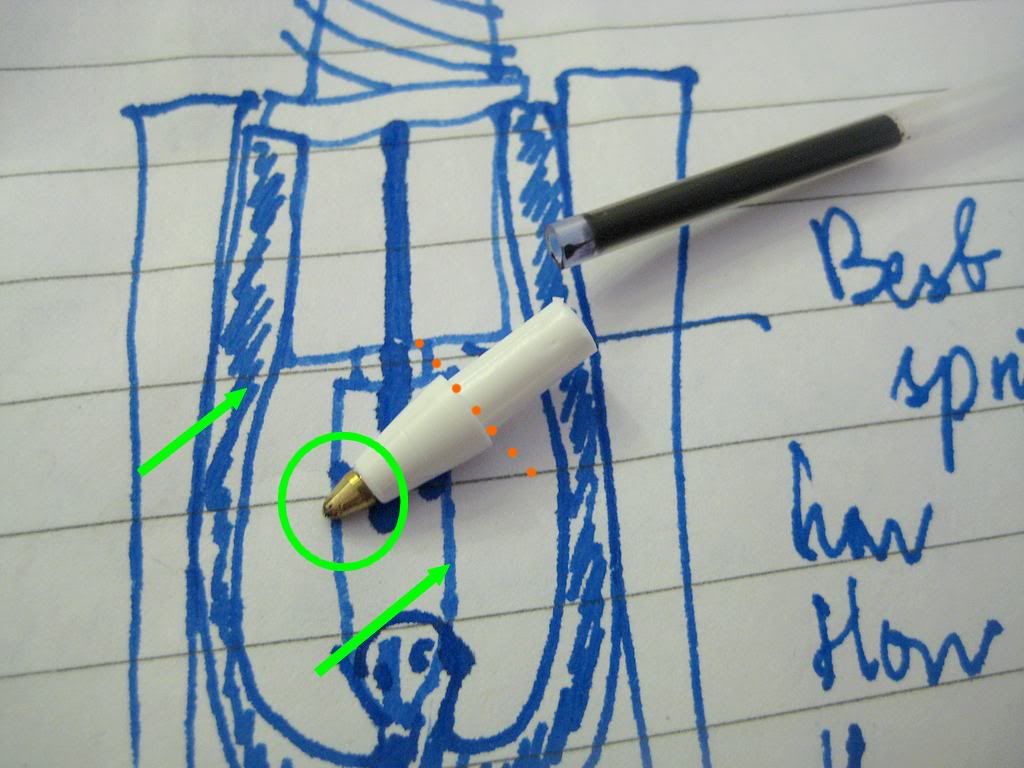
| Reinsert the tip the opposite way around - it will still click into place. Then cut along the orange line to discard the excess plastic. |
 |
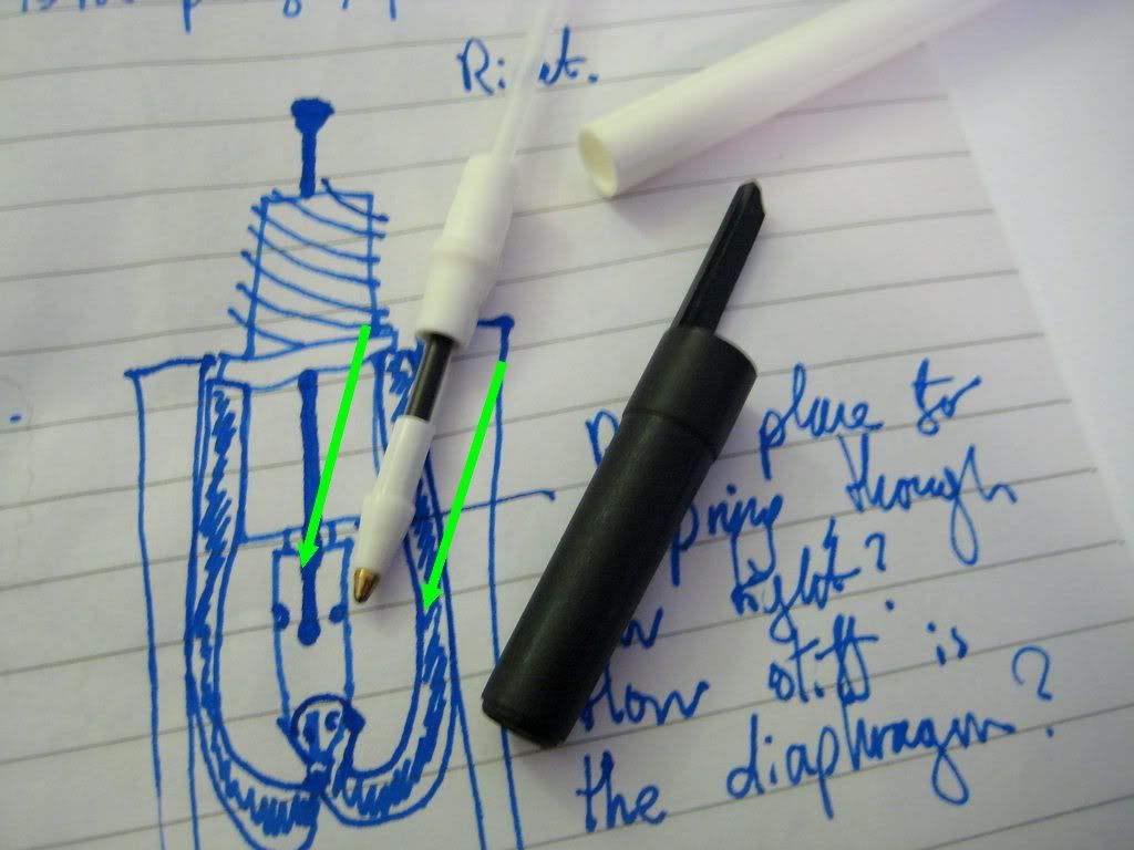
| Heating a length of the ballpoint's ink tube (highlighted) in boiling water. |
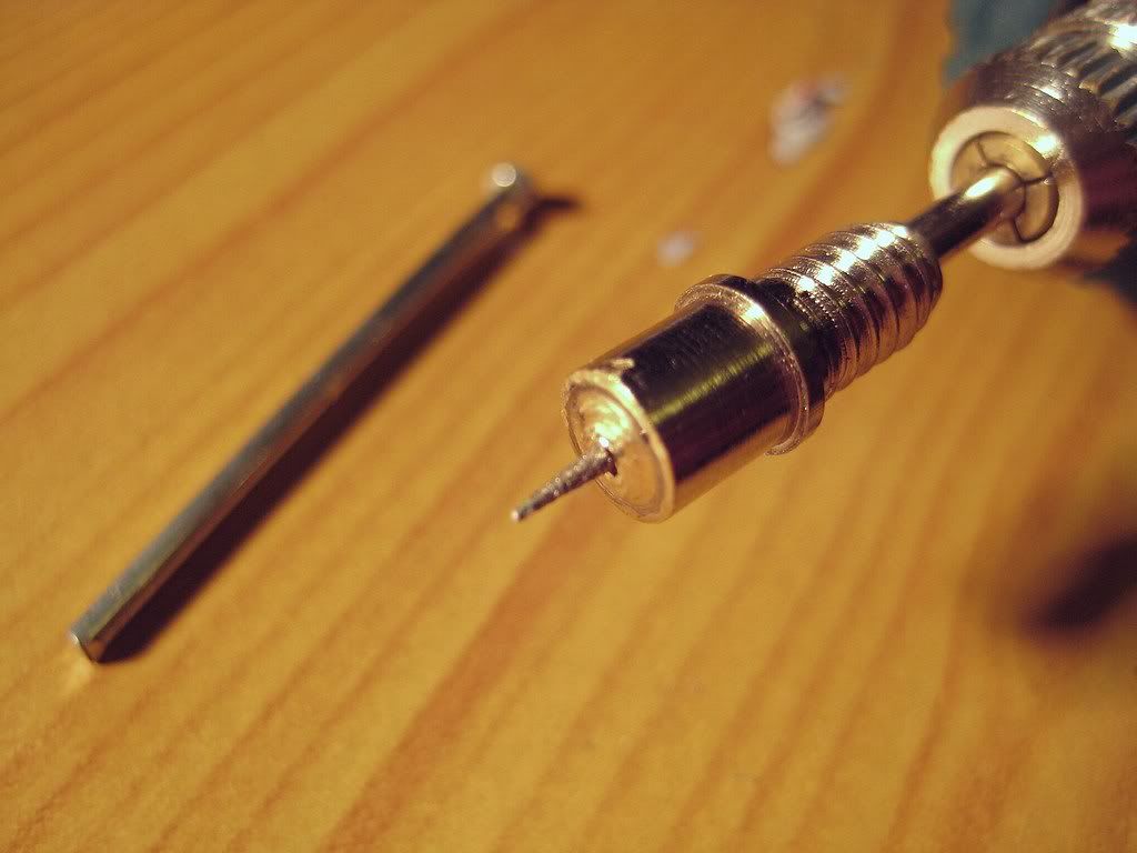
First of all, the rod wants shortening, to minimise wasted barrel space. Secondly, grinding the end to a point greatly helps drive the steel plunger rod into the clear plastic tube.
|
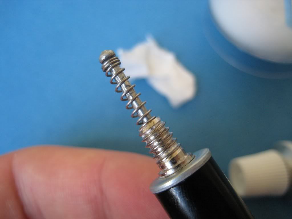
| The exposed end of the steel plunger rod, ready to be driven into the clear plastic tube. |
It's best to put off attaching the pellet holder until after the plunger rod is forced into the plastic tube, to avoid stressing it unnecessarily. Both the exposed end of the plunger rod and the clear connecting tube were cut as short as possible - after all, the less barrel space the filler takes up, the greater the pen's ink capacity.
 |
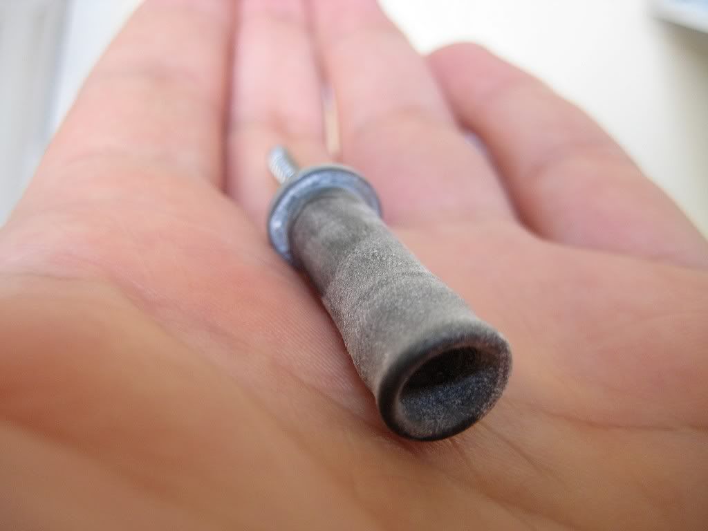
| The plunger rod secured to the ink tube, which acts as a physical stop as well as a connection to the pellet holder. |
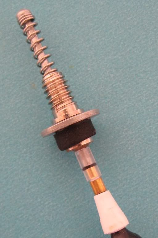 |
| The complete 616 Jumbo vacumatic filler, ready for its diaphragm. |
Hero 616 Vacumatic (4) The Filler Housing
|
| The 616's completed vacumatic filler |
From top to bottom, we have:
The user operated plunger stem,
A return spring,
The filler housing, with external threading for the blind cap,
A steel washer that keeps the filler from falling into the pen's barrel,
Ballpoint pen derived tubing and tip, which connects the plunger stem to...
The white pellet holder, to which the rubber diaphragm (just visible) is later fastened.
The 'filler housing' is a rather grand title given its constituent parts! The vital component is a Woods bicycle tyre valve, for the following reasons.
 |
| A pair of Woods bicycle tyre valves. |
- Unlike the ubiquitous Schrader valve, a Woods valve is small enough to easily fit inside the 616 jumbo's barrel.
- The Woods valve comes with a threaded cap, making the Vac 616's blind cap construction very simple.
- It has a lip before the threaded area, ideal for easy mounting of the assembly to the barrel via a steel washer, with no possibility of pushing it into the pen.
- Its solid metal construction makes for a sturdy filler, minimising flex, slop and lateral play.
- With a little modification, it will allow a rivet tang to pass through it internally as a plunger rod, while being narrow enough externally to act as a physical stop to the flared end of the tang.
- Woods valves cost all of £2.25 a pair. Perfect!
 | ||
| Cutting the valve apart. The piece on the left was discarded. |
 |
| While not strictly necessary, introducing the mini drill's ball attachment to the top of the valve created a nice dished seat for the return spring to sit in. |
The next step was to widen the hole at the bottom of the valve, to accommodate the plunger stem (the tang from a blind rivet). I think it was some sort of solder, or brass or some other soft metal, perfect for smooth and silent movement of metal on metal.
 |
| Widening the hole at the bottom of the valve. |
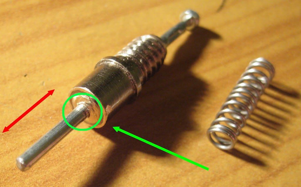 |
| Circled in green, checking plunger stem clearance. The close fit helps prevent lateral slop, allowing only movement in the direction of the red arrow. |
Once the hole was widened, I smoothed out the burr so the rubber diaphragm wouldn't catch on anything sharp when installed later on. It was time to add the steel washer that would top off the barrel, shown in the photo below.
 |
| From left to right: an off cut from a size 16 rubber ink sac, a steel washer, and the valve body. |
Now, even on its own, the washer can't get past the lip on the valve, which is good news. However, its inner diameter is a slightly loose about the circumference of the valve body. To tighten things up, I first pushed a size 16 ink sac off-cut up to the lip of the valve, then forced the washer after it. This made for a centred and very tight fit.
Like this, do you see? First, the off-cut up to the lip of the valve body...
 |
| January Flounder, what were you on about in those diagrams? |
... And the washer forced on after it.
 |
| The washer, pushed tightly up to the lip on the valve body. |
I then trimmed the off cut to about twice the length of the bottom end of the valve, and folded it over (somewhat unevenly, but this excess is hidden from view when the filler unit is complete. The washer is of course perfectly perpendicular to the valve, as the lip acts as a stop, preventing any lopsidedness.).
 |
| The filler housing, ready to accept the pellet holder below, and the plunger stem above. |
Sunday 2 September 2012
Hero 616 Vacumatic (3) Cutting the Blind Cap
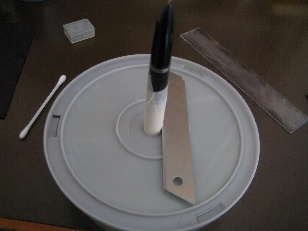
 |
| The 616, ready for blind cap cutting. Circled - spacer washers. |
As before, the barrel was seated in the hollow spindle of an upturned cake of DVD blanks. This time round, though, the cavity was first filled with plastic washers left over from the button filler project. Doing this raised the level of the cavity, so the blind cap was cut higher up the barrel.
How high up? The blind cap had to be long enough to cover the vacumatic plunger stem, and this in turn was governed by the length of the compression spring when at rest. Translation - I guestimated! It came out at about 3.3 centimetres long. This left a decent barrel length to accommodate both the filler and a decent sized ink capacity.
A wrap of masking tape helped protect the barrel from any clumsiness, and I started sawing away. This step is a bit of a chore, and something I chose to spread out over a few days. If you can think up a better way to get a straight cut across a cigar shaped plastic barrel, please drop a line in the comments box below this post.
 | |||
| Sawing the barrel apart! |
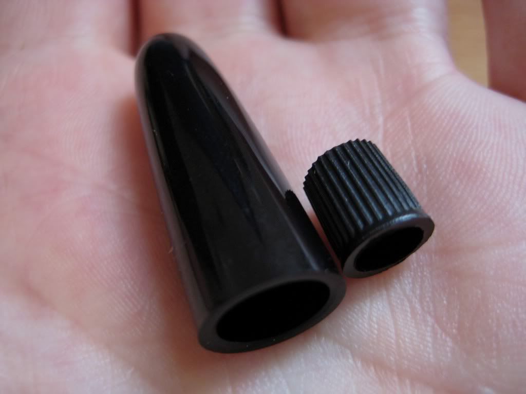 |
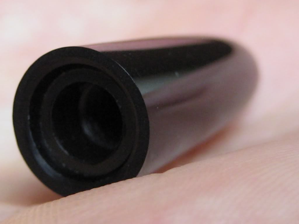
| The revised blind cap, with a Woods valve cap on the right. |
The Woods valve cap is made of soft plastic, and the top can be easily guillotined with a stanley blade. The plunger stem is quite narrow, so the valve cap doesn't require any further hollowing out after the top has been opened to function properly.
 |
| The top of the Woods valve cap, about to face the executioner. |
 |
| The Woods valve cap screwed onto the pen, the vacumatic plunger rod safely clearing through the top. |
 |
| The completed blind cap. |
As there isn't much to this post, I may as well lump in the scrapping of the squeeze-bladder filler.
 |
| Ditching the factory fitted squeeze bladder filler. |
1 - Unscrew the barrel!
2 - Pull the squeeze filler (a steel tube with a bent pressing bar) straight off the ink sac.
3 - Just after the barrel threads, cut the ink sac nipple off.
4 - Cut the breather tube to shorten it (this is so that it will stay clear of the vacumatic diaphragm at full extension, once installed). This example extends 2.9cm from the metal clutch ring on the section.
With the barrel cut, and the blind cap out of the way, we can make a start on what lies beneath it - the next post starts the vacumatic filler build.
Saturday 1 September 2012
Hero 616 Vacumatic (2) Parts and Tools
From the time it leaves the factory, through its brief life meanly doling out that congealed treacle which makes our handwriting such a spidery chore, until its inevitable burial in an overflowing landfill, the ballpoint pen gives uniform dissatisfaction.
Until now! The humble ballpoint makes knocking together a vacumatic fountain pen a breeze. Its ink tube gives an excellent ramrod for the diaphragm pellet. Another piece makes a perfect pellet holder. The tip itself is perfect for connecting the pellet holder to the plunger rod. At a stroke, with no tooling at all, half the vacumatic assembly simply presents itself!
Surprised? I was. Armed with an old ballpoint pen, a washer, a blind rivet, a bicycle tyre valve and an free aftershave sampler, all that is needed to complete the vacumatic assembly is the rubber diaphragm itself.
Parts Used (all prices include UK shipping)
Tools Used
With the parts to hand, it was time to make a start on the conversion, beginning with the next post - "Cutting the Blind Cap".
Until now! The humble ballpoint makes knocking together a vacumatic fountain pen a breeze. Its ink tube gives an excellent ramrod for the diaphragm pellet. Another piece makes a perfect pellet holder. The tip itself is perfect for connecting the pellet holder to the plunger rod. At a stroke, with no tooling at all, half the vacumatic assembly simply presents itself!
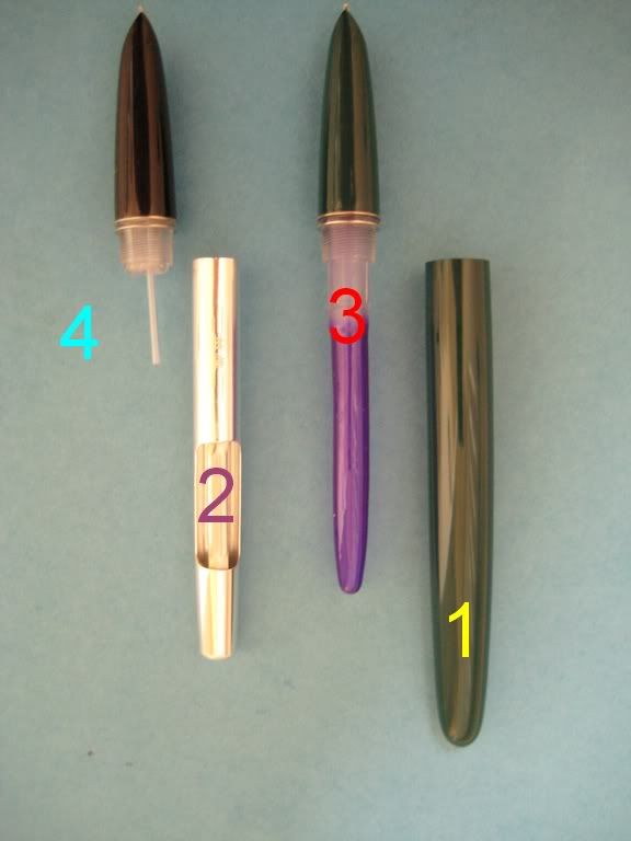
 |
| From left to right: Staedler 430F, Staedler 430M, British Red Cross freebie. |
Parts Used (all prices include UK shipping)
- An old ballpoint pen. This was a freebie from a British Red Cross mailshot. The Staedler Stick 430 seems to be a compatible design too.
- A Dunlop/Woods bicycle valve, and its cap. £2.25 a pair at TemeCycles eBay shop.
- A blind rivet, solely for its tang.
- A free aftershave, eau de toilette, or perfume sampler, the mini spray type, for its tiny compression spring.
- A small metal washer.
- Aquarium sealant (silicon sealant) £3.99 from Maidstone Aquatics.
- A vacumatic diaphragm, the large size (definitely not debutante size) £2.08 from Cathedral Pens.
 |
| The Hero 616 Jumbo uses a much larger vacumatic diaphragm than the Parker 51, as it lacks the latter's dedicated choked barrel chamber. |
Tools Used
- An unbranded mini drill, and the various cutting & sanding attachments they come with.
- A cake of blank DVDs, to hold the curved barrel straight as I cut the blind cap. I don't have a mitre box and had to improvise!
- A sharp, thin utility blade, I think it's the long Stanley type.
With the parts to hand, it was time to make a start on the conversion, beginning with the next post - "Cutting the Blind Cap".
Subscribe to:
Posts (Atom)